The clipper in the loop: overdrive.h
The user-facing chapter claimed that tap.overdrive~'s gain tilts with
frequency and that the tilt grows with drive — behavior a memoryless
waveshaper cannot produce. This appendix derives the loop that produces it,
shows why the obvious implementation of that loop is a stability bomb and how
the file defuses it, and records the design decisions — shaper choice,
asymmetry mechanics, oversampling versus ADAA — with the alternatives they
beat.
The design brief was not a schematic (none is published for the Little Green Wonder, the listening reference): it was the class of TS-lineage feedback overdrives. The honest statement of the goal, from the project's handoff notes: the interesting part is not the transfer curve — it's the frequency-dependent gain and the softer, never-fully-flat knee that a feedback clipper gives you.
The topology, and what it must do
In a TS-lineage pedal the diodes sit in the feedback path of a non-inverting op-amp stage whose feedback network is frequency-dependent. Two consequences:
- The loop gain — and with it the effective clip threshold — varies with frequency: bass sees little gain and stays clean, mids see all of it.
- The output is
input + limited feedback term: even at maximum drive the transfer's slope never reaches zero, because the clean input always passes.
overdrive.h models this with the minimal structure that keeps both traits:
w = shape( G·x − g_fb·LP(w) )      the clipper inside a lowpass feedback loop
y = x + w                          the unity clean path (non-inverting topology)
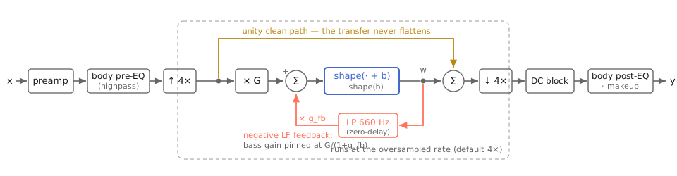
The whole kernel on one line. The red loop is the frequency-dependent gain; the amber path is why the transfer never flattens; everything inside the dashed region runs at the oversampled rate.
G is the drive gain (a dB sweep, +6 to +46). The lowpass LP (one-pole,
corner 660 Hz) makes the fed-back signal predominantly low-frequency, so the
negative feedback suppresses gain exactly where the pedal does. In the linear
region (shape ≈ identity) the loop's small-signal gain is
w/x = G / (1 + g_fb·|LP(ω)|)
— at DC, G / (1 + g_fb); far above the corner, G. The file picks g_fb
from a single voicing constant: g_fb = G/k_lf_gain − 1 with
k_lf_gain = 2, which pins the low-frequency gain at +6 dB regardless of
drive while the mids ride G all the way up. That one line is the measured
headline — a bass-to-mid tilt of +5/+16.3/+17.2 dB at drive 0/0.5/0.9 —
and it is the real-pedal behavior: turning up a TS makes the mids filthier
while the low E barely moves.
Why the loop must be solved zero-delay
The naive discretization feeds back yesterday's lowpass state:
s    = G·x − g_fb·lp_state        // uses the previous sample's state
w    = shape(s)
lp_state += a·(w − lp_state)
That inserts a unit delay into a feedback loop — the same mistake as the
Chamberlin SVF, with the same fuse. Linearize it: the state-to-state map has
Jacobian J = (1 − a) − a·g_fb·shape′. At 48 kHz × 4 oversampling, a 660 Hz
one-pole has a ≈ 0.021; at drive 0.9, g_fb ≈ 62. With shape′ = 1
(small signal — the quiet case!) J ≈ 0.979 − 1.34 = −0.36: stable, fine.
But push g_fb higher — drive 1.0 gives G = 200, g_fb = 99 — and
J ≈ 0.979 − 2.12 = −1.14. |J| > 1: the loop limit-cycles near Nyquist,
audible as a parasitic whine that comes and goes with the signal level.
A feedback clipper that oscillates when you turn it up is not a pedal, it's a
bug report.
The fix is the house zero-delay move (svf.h's driven circuit, ladder.h's
solver_fast): integrate the one-pole trapezoidally (TPT), solve the loop's
linear part implicitly, then apply the nonlinearity and commit its output
to the state. With the TPT one-pole v = (g·w + s)/(1 + g), substitute into
the loop and solve for the node as if shape were identity:
w_lin = ( G·x − g_fb·s/(1+g) ) / ( 1 + g_fb·g/(1+g) )
w     = shape(w_lin + bias) − shape(bias)
v     = (g·w + s)/(1+g);   s ← 2v − s
No delay in the linear loop, so no delay-induced instability at any g_fb;
and because shape′ ≤ 1 everywhere, the committed value only ever reduces
the effective loop gain below the linear prediction — the approximation errs
toward stability. At DC the solve gives w = G·x/(1 + g_fb) exactly, which
is what makes the pinned-bass-gain arithmetic above exact rather than
approximate. The kernel suite pins the consequence: after a full-drive,
full-asymmetry signal stops, the output decays below 10⁻⁶ — no limit cycles.
The shaper: u/√(1+u²), and why not tanh
Three candidates from the brief, in the order they were rejected:
std::tanh— the reference softclip, and the expensive outlier: a transcendental call per (oversampled) sample that vectorizes badly.- Padé-style tanh approximations — cheap, but the usual forms are exact only on a bounded interval and go flat (or worse, retreat) beyond it — reintroducing the hard plateau this design exists to avoid, with a curvature discontinuity at the seam that aliases.
shape(u) = u/√(1+u²)— chosen: C∞ (no curvature seam to alias), strictly monotonic, asymptotic to ±1 but never flat, one multiply-add and one square root — which vectorizes as a reciprocal-sqrt instruction on every SIMD ISA this kernel targets, and reduces to a small LUT for a future fixed-point port.
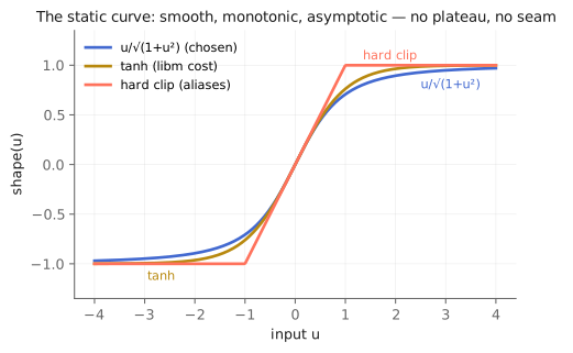
The chosen curve reaches its asymptote more slowly than tanh — softer knee, lower-order harmonics — and unlike the hard clip it has no corner for the spectrum to pay for.
Asymmetry — the even-harmonic control the odd-only Jamoma curves structurally
lacked — is a bias inside the shaper, output-corrected so silence stays
silence: w = shape(u + b) − shape(b) with b = 0.5·asymmetry. At
asymmetry 0 the whole path is an odd function and the measured H2 sits at
the numerical floor (−151 dB); at 0.6 it is −26 dB and musically present.
The correction term keeps the first-order DC out, but a biased clipper still
rectifies: under signal it makes DC, and the feedback one-pole would
happily integrate it. Hence the DC blocker after the clipper —
y[n] = x[n] − x[n−1] + 0.9997·y[n−1], the Jamoma TTDCBlock constant kept
for provenance — permanently in the path, not an option. (The original
TTOverdrive instantiated that same blocker and then overwrote its output
buffer without using it; the vestigial call was one of the tells, noted in
the handoff brief, that the old code path was never going to be the base.)
Oversampling, not ADAA (for now)
Clipping generates harmonics without limit; everything past Nyquist folds
back inharmonically. Two published remedies: oversample the nonlinearity, or
antiderivative anti-aliasing (Parker et al., DAFx-16). ADAA is cheaper per
dB of alias suppression, but its x[n] ≈ x[n−1] fallback branch is hostile
to the branchless-SIMD constraint this kernel inherits from its embedded
targets, and its difference quotient loses precision in single-precision
float — a real concern for the fixed-point/f32 ports. So v1 oversamples:
zero-stuff + 4th-order Butterworth anti-image up, matching anti-alias down —
the ladder.h/svf.h resampler verbatim, self-contained per house rule.
Factors 1/2/4/8, default 4×. Measured on a hard-driven 5 kHz tone: the
folded seventh harmonic improves from −22 dB (1×) to −36 dB (4×) while the
in-band harmonics stay within measurement error. ADAA remains the flagged
experiment for after the voicing locks, so the comparison is apples to
apples.
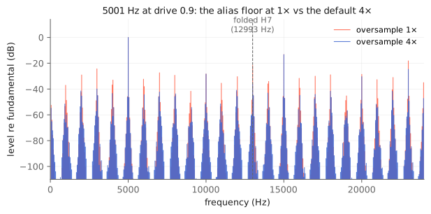
Every red peak standing above the blue mass is inharmonic fold-back the default 4× removes; the true harmonics (multiples of 5001 Hz) coincide in both traces. The dashed line marks the folded seventh harmonic the kernel suite pins.
The voicing layer, honestly labeled
Everything above is structure; the sound of the body control is a handful
of constants (k_voice_* at the top of the file): the pre-clipper highpass
corner sliding 40→320 Hz across the knob, the upper-mid bell at 1150 Hz
(above the classic TS hump — the LGW's push sits higher), the +2.5 dB
counterclockwise treble shelf, the fixed +1.5 dB mid seasoning. They produce
the measured control shape (±10 dB at 100 Hz between extremes, +4 dB at the
bell) and they are by-ear placeholders: the header says so, this book
says so, and the numbers will move when the in-Max voicing pass against LGW
demos happens. What will not move is where they live — all linear EQ outside
the nonlinearity, because in the reference pedal that is what the Body knob
is.
The parameter block is normalized on purpose
drive and asymmetry are 0..1, body is −1..+1; only preamp/output
carry units (dB). The perceptual mapping (dB sweep of G, level
compensation) lives inside the kernel, not in the knob range — so the
parameters map directly to controllers, to live.dial, and to Q15/Q31
fixed-point registers on the Cortex-M targets this library's headers are
written to reach. Parameters ride the standard per-sample linear ramps
(default 20 ms); the derived coefficients — G, g_fb, the solve constants,
the voicing biquads — refresh only on samples where a ramp actually moved,
the same two-tier scheme as svf.h.
Everything in this chapter is executable: the loop math and stability claims
are pinned by tests/overdrive_test.cpp (silence decay, tilt-grows-with-
drive, even-harmonic emergence, DC blocking, alias improvement, determinism),
every number is a cell in
the verification notebook,
and the measured figures are regenerated from the shipping kernel by
book/figures/overdrive.py.