Seventeen, not four: diode_ladder.h
The transistor-ladder appendix derived why the Moog loop oscillates at
k = 4. The 303's filter looks like the same idea — four capacitors, one
feedback path — and behaves like a different species, because the diode
ladder deletes the one luxury the Moog circuit has: buffering. Every diode
pair both charges the next capacitor and loads the previous one. This
appendix derives what that coupling does to the poles, why the oscillation
threshold lands at exactly 17, why the shipping filter still refuses to
self-oscillate at stock settings, and how the coupled nonlinear system is
solved in closed form every sample.
Everything here is verified against Tim Stinchcombe's published TB-303
circuit analysis and the executed
tb303.ipynb
notebook, which matches the kernel's linearized response to his transfer
function to 0.028 dB.
The chain: a diffusion line, not a cascade
With the diode conduction curve linearized (identity for now), the four node voltages obey a coupled chain:
v1' = ω·(S(u − v1) − S(v1 − v2))
v2' = ω·(S(v1 − v2) − S(v2 − v3))
v3' = ω·(S(v2 − v3) − S(v3 − v4))
v4' = 2ω·S(v3 − v4)          [the top capacitor is halved on the schematic]
Each middle equation has two terms — charge in from the left, charge stolen by the right. That is the loading, and it is the whole story: this is a discrete diffusion line, not four independent one-poles.
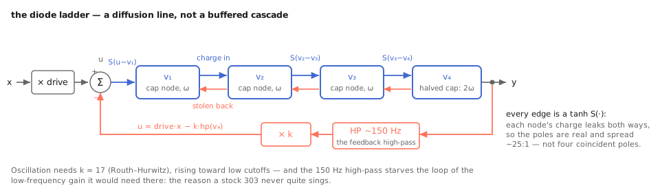
Every edge is a tanh; every middle node leaks both ways. The bidirectional arrows are what a buffered cascade doesn't have — and why the poles spread. Its normalized transfer function works out to exactly Stinchcombe's measured TB-303 response,
H(s) = 1 / (s⁴ + 6.727·s³ + 14.142·s² + 9.514·s + 1)
and the coefficients are not arbitrary — they are 4·2^(3/4), 10·√2,
8·2^(1/4): the equal-component chain with the top cap halved, which is
also why Stinchcombe finds that changing that one cap shifts cutoff by
2^0.25. The poles are all real and spread ~25:1 (−0.13, −1.04, −2.33,
−3.24 normalized). Compare the Moog ladder: four coincident poles.
Consequences you can hear:
- Asymptotically the slope is 24 dB/oct, but only ~14 dB falls in the first octave above cutoff — the honest version of the panel's "18 dB" claim.
- At resonance 0 the −3 dB point sits ~3.2 octaves below the resonance
frequency. The kernel's
frequencyparameter names the resonance peak, and the wide skirt below it is the real filter, not a tuning bug.
Seventeen: the closed loop's threshold
Feedback enters as u = drive·x − k·hp(v4). Ignore the high-pass for a
moment and run Routh–Hurwitz on the closed loop: the stability boundary
lands at exactly k = 17, with the marginal oscillation at √2× the
stage rate. (Open303 normalizes its feedback by the same 1/17.) So
resonance maps k = 17·resonance, putting 1.0 at the ideal chain's
threshold — and the prewarp is chosen so that the √2 factor lands the
oscillation on the labeled frequency:
g = tan(π·fc / fs_os) / √2 per stage (2g on the top stage)
Why a stock 303 never quite sings
Now put the high-pass back. The hardware's resonance feedback runs through a
~150 Hz one-pole high-pass (Open303's calibrated value, the fbhp default),
and its phase lead pushes the would-be oscillation frequency up — to where
the ladder attenuates more. Measured on the shipping kernel: the closed loop
needs k ≈ 17.5 even at 8 kHz, ≈ 19 at 2 kHz, ≈ 25 at 500 Hz. The knob
stops at 17. The emergent result — not programmed, derived — is the famous
trait: a stock TB-303 never quite self-oscillates, and neither does this
filter until you take the documented bend (resonance runs to 1.5, i.e.
k = 25.5; past ~1.1 it sings at high cutoffs, slightly sharp of fc for the
same phase-lead reason).
The high-pass buys two more behaviors for free:
- Resonance thins as cutoff falls — low notes squelch instead of ringing, which is why a 303 keeps its bass at high resonance.
- Closed-loop DC gain is exactly 1 regardless of resonance. The
transistor ladder needed a
compparameter to buy its passband back; the 303's own circuit is the compensation, so this kernel has none.
Set fbhp 0 and the ideal analysis becomes exact: threshold at 1.0,
oscillation at fc, drifting flat by ~0.7× the resonance excess past
threshold — an amplitude effect (the growing swing saturates the edges
unevenly), identical at every cutoff, and pinned by test.
The nonlinearity lives on the edges
In the circuit the coupling elements saturate — there are no buffer amps
between stages to saturate instead. So the kernel puts tanh on every
S(·) above: four saturators, one per diode-pair edge, slope 1 at the
origin so small signals see exactly the linearized Stinchcombe response.
There is no asym parameter here, deliberately: the diode pairs are
complementary, so the transistor ladder's operating-point-mismatch story
does not apply.
Solving the coupled system in closed form
The ZDF discretization (trapezoidal, as everywhere in the house) turns each
sample into a system: five unknowns (v1..v4 and the loop input u)
that all depend on each other through the couplings and the feedback. The
kernel linearizes each edge with a secant gain γ = tanh(e)/e at an
operating point, and then — this is the part worth reading in the code —
eliminates the linear system bottom-up to closed form: v4 in terms of
v3, then v3 = p30 + p32·v2, v2 = q20 + q21·v1, back-substituted until
one division yields v1 and everything else follows. No matrix, no pivots,
and unconditionally stable: every divisor is ≥ 1 for g > 0, γ ∈ (0, 1].
The feedback high-pass's state enters the same solve (its instantaneous
gain 1 − G multiplies k), so the loop is closed exactly, high-pass
included.
The two solvers differ only in how the secant gains chase the operating point:
solver_fast(default): solve at the previous sample's gains, refresh the gains at that solution, solve once more, commit.solver_exact: repeat the refresh-and-solve until the node voltages move by less than 1e-12 (capped at 32 iterations).
Measured across a settings matrix out to resonance 1.4 and +24 dB drive —
beyond hardware reach — the worst-case difference is −44.9 dBr, at
1.6–3.3× the CPU. The fast path's one correction is almost always enough
because tanh is smooth and the operating point moves slowly at audio rate;
the exact path exists so that claim never has to be taken on faith.
After the solve, the states advance trapezoidally using the true diode
currents (tanh at the solved voltages, not the secant approximations) —
the same "linearize to solve, commit with the real nonlinearity" pattern as
ladder.h's one-pass commit.
Oversampling and the rest of the housekeeping
tanh generates harmonics; harmonics alias. The kernel runs 1×/2×/4×
(default 2×) with zero-stuffing and matched 4th-order Butterworth
anti-image/anti-alias cascades — the ladder.h pattern, self-contained here
per the house rule against shared lookup tables. Every parameter rides a
per-sample linear ramp; 16 preset slots morph through the same ramps; the
right-inlet path recomputes the coefficient per sample for signal-rate
cutoff. All state clears to zero, and all-zero state is a fixed point — a
self-oscillating patch needs a ping, exactly like the transistor ladder.
The engineering ledger
- Coupled solve vs. buffered shortcut. A "diode ladder" built from four buffered one-poles with new constants would miss the pole spread — the defining character. The 2×-larger algebra of the coupled solve is the price of the topology, paid once in closed form.
- Secant linearization vs. Newton. Newton needs the derivative of five
tanhterms through the elimination; secant gains reuse the same elimination unchanged and converge fast enough thatsolver_exactrarely iterates more than a few times. Same accuracy target, simpler code. - WDF: the documented no-go. A wave-digital rebuild of the same network
was evaluated and declined (author-approved, 2026-07-18):
solver_exactalready converges the circuit's nonlinear equations, and a WDF would re-solve the same network differing only through the Shockley-vs-tanh diode curve, with no measured reference showing an audible delta to chase. The evidence lives in the notebook's solver A/B matrix. - No
asym, nocomp. Both absences are circuit facts, not omissions: complementary diode pairs, and a high-pass that is its own passband compensation.
Checkpoint
A diffusion chain whose transfer function matches the published analysis to 0.028 dB, with the oscillation threshold derived at k = 17 and then — because the feedback high-pass is modeled rather than idealized away — never reached at stock settings, exactly like the hardware. The nonlinearity sits on the coupling edges where the circuit puts it; the coupled ZDF system is eliminated to closed form and solved once or iterated to convergence, with −44.9 dBr between the two answers at settings the hardware can't reach. The character is the coupling, and the coupling is solved, not approximated away.